
How to Measure over NAT
NAT changes packet content, which brings a new challenge on passive QoS measurement. However, Qosium can manage this and you can measure QoS over a network path where there is a NAT deployed between.
Contents
1. Define the Topology #
There are a couple of specific actions you need to take in the parameterization when measuring over a NATNetwork Address Translation
A technique for remapping an IP address space or proxies that change the protocol header content of IP packets. The following instructions tell how to do the measurement parameterization with Qosium Scope. Qosium Scopemon and Scope Lite has the corresponding parameters and the procedure is the same than with Scope.
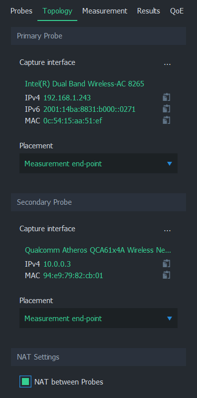
On the bottom of the Topology tab, enable NAT between Probes as shown below.
2. Set the Filter #
Filtering differs from the typical measurement scenario where a NAT is not present. There are two ways how to set the filter. In the most common one, set the filter how the Primary Probe sees the traffic flow(s), while the secondary Probe filter is set automatically. Alternatively, you can define a complex filter that includes parts for both sides of the NAT. This, naturally, requires that you are aware of how the desired traffic looks on the other side of the NAT.
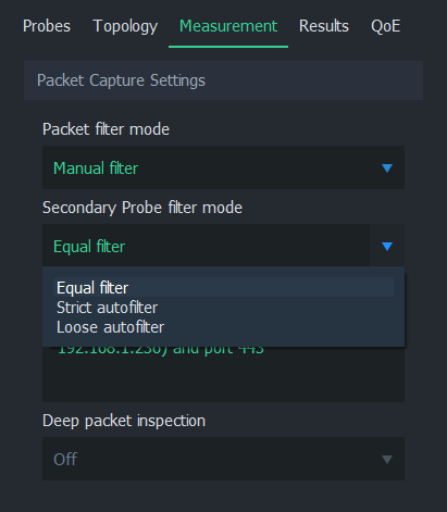
Give Packet filter manually in the Measurement tab. After selecting Manual filter, you have three options in the Secondary Probe filter mode selection.
2.1. Loose autofilter #
Use this when you wish to include all the flows between two IP addresses in the measurement. Define only the IP addresses in the filter. Do this from the primary Probe perspective – the secondary Probe filter is calculated automatically.
If, for example, IP addresses of the interesting traffic flows (as seen from the perspective of the Primary measurement point) are: 192.168.0.100 and 10.0.0.10, then the filter here would be:
ip and host 192.168.0.100 and host 10.0.0.10Thus, the general format of the filter to set here is:
ip and host <IP address 1> and host <IP address 2>2.2. Strict autofilter #
Use this when you wish to measure the QoS of only a single flow between the two measurement points. In addition to IP addresses, use source and destination port definitions and also add the transport level protocol in the filter. This ensures that only a single flow will hit the filter. Do this from the primary Probe perspective – the secondary Probe filter is calculated automatically.
If, for example, the interesting traffic flow is TCP 192.168.0.100:56838 <=> 10.0.0.10:8177 as seen from the perspective of the Primary measurement point, then the filter here would be:
ip and tcp and host 192.168.0.100 and port 56838 and host 10.0.0.10 and port 8177Thus, the general format of the filter to set here is:
ip and <protocol> and host <IP address 1> and port <port 1> and host <IP address 2> and port <port 2>2.3. Equal filter #
This selection means that exactly the same filter is used in both measurement point ends. Use this option if you want to measure something between all traffic and a single flow over a NAT. As known, NAT will change the addressing and ports of the traffic, so a single-flow filter won’t do the trick. It is, of course, possible that there is something similar and also unique in the desired traffic that remains over the NAT, allowing you to generate a simple filter based on that. Generally, however, that is not the case. Thus, typically, you need to define a two-part filter:
<filter for the desired traffic in the Primary end> or <filter for the desired traffic in the Secondary end>Since especially the latter part of the filter can be quite troublesome to conclude, Loose autofilter or Strict autofilter are typically being used.
 A handy way to check how the desired traffic looks at both measurement points over the NAT is to use two additional Qosium Scopes. Set them to single-point measurement mode to measure both points. The flow views reveal how the flows look. You can also test the filter you are building with the single-point measurements. When the filter is ready, using it shows only the desired traffic on both ends.
Glossary >
Network Address Translation
A technique for remapping an IP address space